Updated
Once the mechanism is clear, see the Read the turbocharger overview for the architectural breakdown of the three variant families (wastegate, variable-geometry, twin-scroll) and the three primary failure modes.
The Thermodynamic Loop in Plain Language
A turbocharger is a self-contained thermodynamic loop: exhaust gas energy goes in, compressed intake air comes out, and the rotating-mass shaft does the work in between. Energy that would otherwise exit the tailpipe as waste heat (40-60% of total combustion energy) gets captured to drive useful compression.
The exhaust manifold routes 1,400-1,700°F exhaust gas through the turbocharger's turbine housing. Inside the housing, the gas strikes a turbine wheel — typically 8-12 curved blades on modern OEM passenger-car frames — and imparts rotational energy to a shaft that passes through the center bearing cartridge to the compressor housing on the other side. The compressor wheel — typically 6-8 curved blades — pulls ambient air at atmospheric pressure (14.7 psi) into the housing and accelerates it through a diffuser before delivering it to the intake manifold at the boost target pressure (15-22 psi on OEM gasoline, 18-30 psi on OEM diesel).
The intercooler sits between the compressor outlet and the intake manifold, cooling the compressed air from 250-400°F at the compressor outlet down to 90-140°F at the throttle body. Cooling the charge air increases its density, allowing more oxygen mass per unit volume into the cylinders. Most modern OEM applications use air-to-air intercoolers mounted at the front of the vehicle; some performance-oriented OEM applications (BMW M-series, Mercedes-AMG) use air-to-water intercoolers integrated into the intake manifold for faster response.
"The number that surprises most people: a modern OEM turbocharger spins at 100,000+ RPM under load. The compressor wheel tip speed approaches the speed of sound at peak boost. That's why oil supply discipline is non-negotiable — at that RPM, the bearing oil film is the only thing between functional turbo and catastrophic failure." — r/cars synthesis on the rotational speeds of modern factory turbochargers.
The Six Structural Components
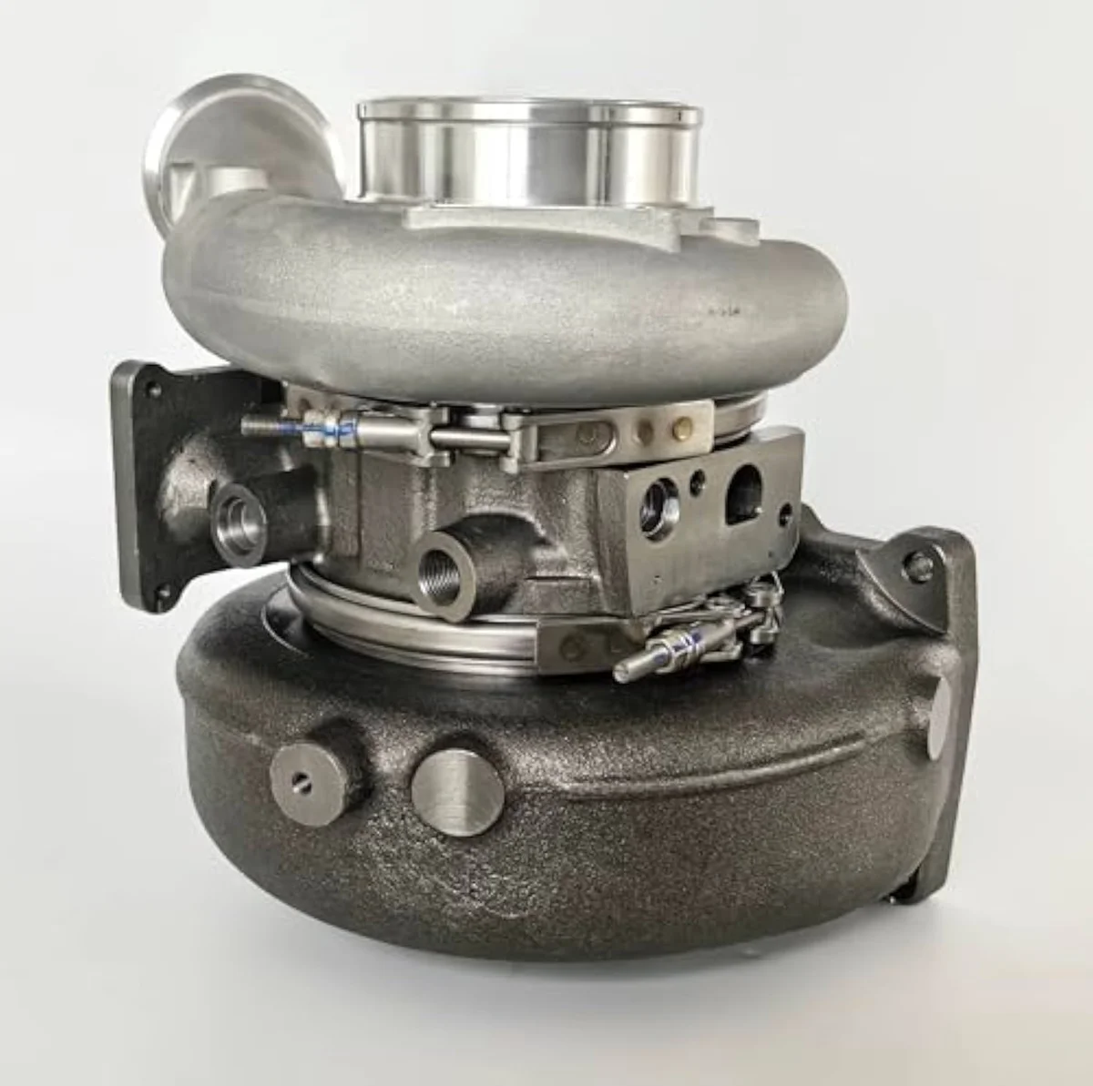
Every turbocharger — OEM Garrett GT1446V on a Cruze, OEM Holset HE351VE on a Cummins 6.7L, or aftermarket Precision PT6266 on a Honda B-series — contains six structural components: turbine housing, turbine wheel, compressor housing, compressor wheel, center bearing cartridge, and wastegate or variable-geometry actuator.
Turbine housing (the exhaust side): heavy iron casting, sized by A/R ratio (area-to-radius ratio of the volute, typically 0.48-1.05 on passenger-car frames). Smaller A/R = faster spool, lower peak flow; larger A/R = slower spool, higher peak flow. Turbine wheel: typically Inconel 713C or 713LC alloy to withstand 1,800°F sustained temperatures, 8-12 blades, dynamically balanced to ISO grade. Compressor housing (the intake side): aluminum casting, sized by trim and inducer dimensions. Compressor wheel: aluminum or billet aluminum, 6-8 blades, balanced to match the turbine wheel mass on the shared shaft. Center bearing cartridge: contains the journal or ball bearings, oil and coolant passages, and shaft seals. Wastegate (fixed-geometry frames) or variable-geometry actuator (VGT diesel frames): the boost-control mechanism.
The Boost Pressure Cycle Across the RPM Band
Boost pressure rises non-linearly across the engine RPM band. From idle to roughly 2,200-3,500 RPM (the spool-up band, varying by frame size), the turbo produces little to no boost; the engine drives like its naturally aspirated displacement. Above the spool-up band, boost rises rapidly to the wastegate target (15-22 psi on most OEM gasoline applications) and holds steady through the rest of the RPM range until the rev limiter.
The spool-up RPM threshold is set by exhaust mass flow versus the turbine wheel's mass moment of inertia. A small turbo (low-A/R turbine housing, light wheels) spools at 1,800-2,400 RPM but chokes at 4,500-5,500 RPM. A large turbo (high-A/R, heavy wheels) spools at 3,000-4,000 RPM but holds boost cleanly to 7,000+ RPM. OEM applications usually pick a small frame for daily-driver responsiveness; performance aftermarket usually picks a larger frame for peak power. Variable-geometry diesel applications get both — fast spool at low RPM (vanes closed for high exhaust acceleration) AND high peak flow (vanes open for full exhaust passage).
The wastegate manages peak boost by bypassing excess exhaust around the turbine wheel above the target. A spring-pressure wastegate (manual control) holds the spring's preload as the boost target; a vacuum or pressure-modulated wastegate (electronic control via the ECM) holds the programmed boost target. Modern OEM applications run electronically controlled wastegates that target different boost values per gear, throttle position, and EGT condition.
Why Oil and Coolant Supply Discipline Matters
The center bearing cartridge contains the most critical components. Pressurized engine oil (typically -3 or -4 AN supply line, 1.0-1.4 mm internal restrictor on ball-bearing frames, no restrictor on journal-bearing frames) forms a hydrodynamic film between the shaft and the bearing housing. Without oil flow, the shaft contacts the bearing surface at 80,000-150,000 RPM and the bearings fail in seconds.
Coolant flow through the bearing housing prevents oil coking from the 1,400-1,700°F exhaust-side heat soak. Without coolant, the oil in the bearing housing bakes into carbon during heat-soak after engine shutdown, eventually clogging the oil passages and starving the bearings on the next startup. The coolant passages are typically -10 AN or -12 AN with no restrictor; the system is designed to thermosiphon for several minutes after engine shutdown, carrying residual heat away from the bearing housing.
Install errors that violate the oil and coolant discipline are the #1 cause of premature aftermarket turbo failure across every brand tier. Undersized supply line, oversized restrictor on a journal-bearing frame, restricted return drain (sharp bends, inline filters, extension hose runs), or missing coolant supply all destroy the bearings within 10,000-30,000 miles. Garrett, Precision, BorgWarner, and Holset all void the warranty for documented install errors of this type. The right install discipline is published in each manufacturer's tech library and matches OEM service-manual procedures on the supplied chassis.
For the deeper engineering background, the Turbocharger reference covers the thermodynamic loop, compressor-and-turbine architecture, and historical development. The Wastegate reference covers internal-vs-external wastegate architectures and the spring-vs-electronic control variants. The Turbo University reference publishes industrial-tier balance-and-test discipline for the bearing cartridge. The Understanding Turbochargers Guide covers the rebuilder-tier protocol shops apply across passenger-car and heavy-duty applications.
For the specific application-side cross-shop after the mechanism is clear, the Read the cross-engine roundup covers documented OE-replacement and performance picks across Cummins 6.7L, Ford EcoBoost 2.0L, and Chevy Cruze 1.4L chassis lanes. For the budget-tier T3/T4 universal frame that this mechanism explainer references, the Read the Maxpeedingrods T3/T4 review covers the entry-tier aftermarket performance path.
Mechanism Decision Questions
- How does a turbocharger increase engine power?
- A turbocharger packs more air into the cylinders than atmospheric pressure alone allows. More air enables proportionally more fuel injection while maintaining the correct air-fuel ratio (typically 12.5-14.7:1 on gasoline applications), and more fuel per combustion cycle equals more horsepower. A 2.0-liter engine at 18 psi of boost ingests roughly twice the air mass per cycle of the same engine naturally aspirated, producing 25-100% more peak horsepower at the cost of higher cylinder pressures and exhaust gas temperatures.
- What spins a turbocharger?
- Exhaust gas flow spins the turbine wheel. The exhaust manifold routes 1,400-1,700°F exhaust gas through the turbo turbine housing, where it strikes the curved turbine blades and imparts rotational energy to the shared shaft. The compressor wheel on the other end of the shaft spins at the same RPM (typically 80,000-150,000 RPM under load) and compresses ambient intake air into the engine. The system is a self-contained thermodynamic loop driven entirely by exhaust energy that would otherwise be wasted.
- What is a wastegate and what does it do?
- A wastegate is a pressure-control valve that bypasses excess exhaust gas around the turbine wheel to limit peak boost pressure. Below the boost target, the wastegate stays closed and 100% of exhaust gas drives the turbine. At the boost target, the wastegate opens proportionally to bypass enough exhaust gas to prevent further pressure rise. Without a wastegate, the turbo would over-spin under load and either damage itself or destroy the engine with excessive cylinder pressure. Wastegates can be internal (integrated into the turbine housing) or external (separate valve mounted upstream).
- What is a variable-geometry turbocharger?
- A variable-geometry turbocharger uses moveable vanes inside the turbine housing to change the effective turbine-housing geometry on demand. At low engine RPM, the vanes close down to accelerate exhaust gas through a smaller cross-section (faster spool, lower lag). At high engine RPM, the vanes open up to allow full exhaust flow (peak power, no choke). The architecture is standard on modern diesel applications (Cummins 6.7L HE351VE / HE300VG, Ford 6.7L Power Stroke GT3782VAS, BMW N47 / Mercedes OM651) and increasingly common on gasoline applications via the Honeywell-AVNT design.
- What is turbo lag?
- Turbo lag is the delay between throttle input and boost arrival. Below the spool-up RPM band (typically 2,200-3,500 RPM depending on frame size), the turbo produces little to no boost because the exhaust mass flow has not built up to drive the turbine wheel effectively. Above the spool-up band, boost arrives rapidly. Variable-geometry turbos reduce lag by accelerating exhaust gas at low RPM. Ball-bearing center cartridges reduce lag by 15-25% versus journal-bearing equivalents on the same frame. Twin-scroll exhaust manifolds reduce lag by eliminating exhaust pulse interference at low RPM.
- What is boost pressure measured in?
- Boost pressure is measured in pounds per square inch (psi) above atmospheric pressure in US markets, and in bar in European and Asian markets (1 bar ≈ 14.5 psi). Typical OEM boost targets: 15-22 psi on modern gasoline applications (Ford EcoBoost 2.0L, BMW B58 3.0L, Mercedes M139 2.0L), 18-30 psi on heavy-duty diesel applications (Cummins 6.7L, Ford 6.7L Power Stroke), and 25-45 psi on aftermarket performance builds. Some race-only applications run 50+ psi at the cost of dramatically shortened engine life.
- Why do turbochargers need oil and coolant?
- The center cartridge bearings need pressurized engine oil to form a hydrodynamic film between the shaft and the bearing housing — without it, the bearings dry out and fail in seconds under 80,000-150,000 RPM rotation. Coolant flow through the bearing housing prevents oil coking from the 1,400-1,700°F exhaust-side heat soak — without it, the oil bakes into carbon and clogs the bearing oil passages. Both supply lines are critical; routing failures or restrictor mistakes cause more aftermarket turbo failures than any other install error.
Get Product Updates
Updates only when something changes.
Only when something changes. Unsubscribe anytime.